3-DOF Helicopter Control System Design
For the final capstone project in the avionics stream of my Aerospace Engineering program, we were tasked with getting a Quanser 3-DOF helicopter to: take off, travel to a wall, drill three holes, return to base, and land. The actual project wrapped a lot of things I enjoyed at the time into one system: modeling, PID control, trajectory planning, signal processing, MATLAB/Simulink, GUI design, and a good amount of debugging real hardware.
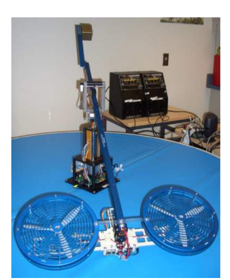
The requirements for the final deliverable were:
- elevate smoothly to the horizontal position while recording overshoot and steady-state error;
- travel 90 degrees in 10 seconds while keeping tracking errors small;
- drill three holes, 10 mm apart, in a wall placed roughly 100 degrees from the starting position.
On top of that, the system needed a simulator, a controller design process, signal processing for the sensors, and a user interface that made the whole thing operable without digging through the Simulink model during a live run. For the latter, fully-remote operabiilty was also a requirement and hence the interface had to track realtime telometrics. Me being me, I couldn't help but add a learn-and-play mode where the operator could manually guide the helicopter arm through a trajectory, record it, and then play it back autonomously.
The system
The helicopter had three main degrees of freedom: elevation, pitch, and travel. The encoders gave us the measured angles, and the motors were driven through voltage sum and voltage difference commands. The drilling attachment added another layer of fun: an infrared sensor to detect the wall and a limit switch to tell us when the drill had passed through.
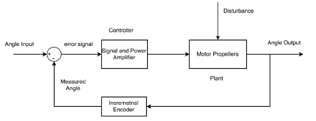
The project ended up being less like "design a controller" and more like "make a collection of subsystems behave like one system":
- identify and model the elevation, pitch, and travel dynamics;
- design PID controllers and tune them on the real plant;
- filter encoder and drill sensor signals;
- build a simulator that was good enough to be useful;
- create a single Simulink file that could support multiple mission modes;
- build a GUI for set-point control, manual control, remote control, drilling status, testing, and learn-and-play;
- stitch all the mission logic together without the helicopter doing something surprising at the worst possible time.
Modeling and control
We started with analytical and experimental models for each axis and used those models to design initial PID controllers. The initial controller design was based on root locus methods, but the real system still needed a lot of manual tuning. That was probably the first lesson of the project: the model can get you into the right neighborhood, but the plant still has the final say.

The axes had different personalities. Elevation needed to settle quickly with little overshoot, especially because the helicopter would dip when the drill exited the wall. Pitch mattered because it directly affected travel acceleration. Travel was the trickiest to think about in isolation because it was tied to trajectory planning: the helicopter needed to move 90 degrees in 10 seconds and keep tracking error below about 3 degrees.
One thing I still like about this project is that it made the control tradeoffs very concrete. The gains that worked well for trajectory tracking were not necessarily the gains that behaved best during drilling. Wall contact, drill vibration, and exiting the hole added disturbances that made stability more important than raw tracking performance. So the final system used different controller settings depending on what the helicopter was trying to do.
The GUI
The GUI was not just a nice front-end. It was the thing that made the system usable. Without it, operating the helicopter would have meant clicking around a fairly involved Simulink model while a real physical system was running. That seemed like a pretty good way to make mistakes.
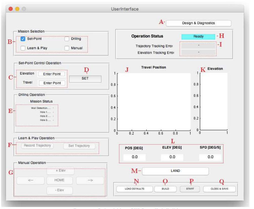
The interface let the user select missions, enter set-points, start and stop the model, monitor travel/elevation/speed, see drilling status, load default controller and filter parameters, and manually override the helicopter. Building the GUI early was useful because it forced the Simulink model and the interface to evolve together. It also made debugging much easier because the important signals were visible in one place and made testing different configurations simple; something my teammates really appreciated.
Mission logic
The drilling mission was the most interesting part. A simple set-point controller was not enough; the helicopter had to move through a sequence of states: take off, reach level flight, travel toward the wall, detect the wall, slow down, contact the wall, drill, back out, change elevation, repeat, return home, and land.
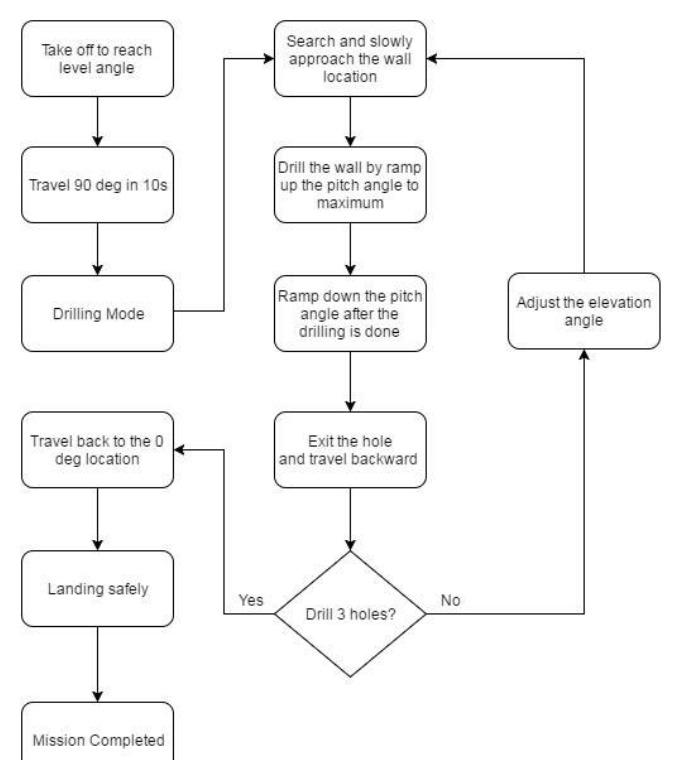
Originally, the plan was to detect the wall and then continue into a slow approach. In practice, bouncing on contact was a real issue. The better approach was to detect the wall, retreat a little, stabilize, and then approach more slowly after switching to a dedicated close-approach configuration. It was a small change in logic, but it made the second and third holes much more repeatable.
For the travel motion, we used a cubic polynomial trajectory rather than a step input. The idea was to give the system a smoother velocity and acceleration profile so it could reach the target without asking the pitch and travel controllers to do something unreasonable.
How it went
Overall, the system worked: the helicopter elevated to steady level flight, traveled toward the wall, searched for it, drilled three holes, returned to base, and shut itself off. We also demonstrated manual set-point control, manual override, and the bonus learn-and-play mode.
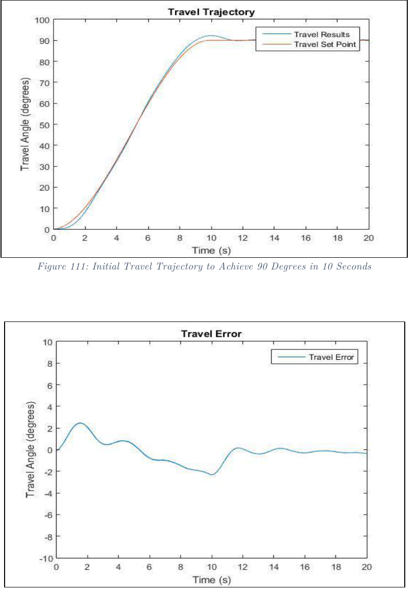
The approach phase had almost no overshoot or steady-state error and settled in about 4.2 seconds. The 90 degree travel segment had a maximum tracking error of about +2.8 degrees near the beginning and -2.1 degrees near the end. Accounting for the recovery from those errors, the 10 second trajectory took closer to 11.3 seconds in the final run.
The drilling worked, but not perfectly. The first and second holes ended up 1.2 cm apart, while the second and third were 1 cm apart as required. Earlier testing had produced three holes spaced 1 cm apart, but the final run exposed how sensitive the first hole was to bouncing and the infrared sensor's detection range. That feels like a very honest hardware lesson: the system can satisfy the requirement in principle and still reveal a weak point under demo conditions.
The learn-and-play mode was also a proof-of-concept, but it was a fun one. During teaching, the encoder data was sampled at the system sample time of 0.002 seconds while the arm was moved by hand. Even tiny hand motions showed up in the data, so I applied a moving average filter before using the recording as a playback trajectory. It was noisy and preliminary, but the helicopter could follow the taught motion closely enough to show that the idea worked.
Looking back
This project was a nice reminder that real systems are held together by much more than the main algorithm. The controller matters, but so do the filters, interface, mode switching, sensor quirks, safety behavior, and all the boring little bits of glue that make the demo actually run. Clean block diagrams are useful, but the interesting part is what happens when they touch a physical system.
There are lots of things I would improve now. I would spend more time on the wall-detection logic, make the mission state machine cleaner, filter the learn-and-play trajectories more carefully, and probably be more systematic about the controller switching. Still, for a capstone project, it was a pretty satisfying proof-of-concept.
Here is the original demo video: